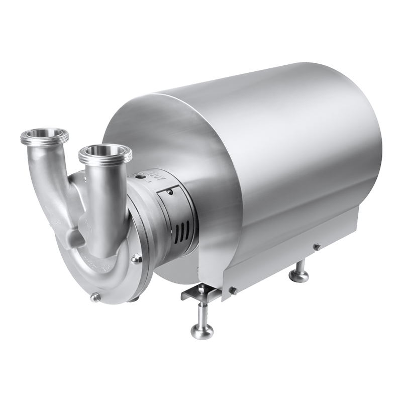
In hygienic processing environments where product integrity and cleanability are non-negotiable, the single-rotor positive displacement pump with its waveform geometry has become an established choice for transferring shear-sensitive fluids, soft particulates, and high-viscosity products. The mechanical simplicity of this design—one rotor, one liner, no timing gears—contributes to a maintenance profile that is often less demanding than that of multi-rotor alternatives. Yet this simplicity does not eliminate the need for a structured maintenance program. On the contrary, the same design features that reduce the number of wear components also mean that when wear does occur, it concentrates at specific, predictable locations. Understanding these locations and the conditions that accelerate degradation at each one is the basis for a maintenance strategy that maximises service life.
The rotor, typically manufactured from stainless steel with a surface finish below Ra 0.8 μm, rotates within a precision-machined liner that matches its waveform contour. The shaft seal assembly forms the barrier between the process fluid and the atmosphere, and the bearing housing supports the shaft on the non-process side. Each of these components experiences different loading conditions and is susceptible to different failure mechanisms. A preventive maintenance program that addresses each zone according to its specific risk profile reduces unscheduled downtime and extends the interval between major overhauls.
Mechanical Seal Care: Preventing the Most Common Failure Mode
The mechanical seal is the most frequently serviced component in any positive displacement pump, and the single-rotor design is no exception. The seal consists of a stationary face fixed in the pump housing and a rotating face mounted on the shaft, with a fluid film measured in microns separating the two. This film is maintained by the process fluid or, in some configurations, by an external flush. When the film is disrupted, the seal faces contact each other, generating heat and wear that quickly leads to leakage.
Dry running is the most damaging condition a mechanical seal can experience. Even a few seconds of operation without fluid in the pump housing can elevate the seal face temperature to the point where the materials crack or deform. Ensuring the pump is adequately primed before starting—and that upstream supply valves are confirmed open—is a fundamental operating discipline that protects the seal. In systems where the pump may run intermittently, a low-level interlock that prevents starting when the supply tank is empty adds a layer of protection.
Thermal shock is a less obvious but equally damaging condition. In processes that run a hot clean-in-place cycle followed by a cold product changeover, the rapid temperature change can cause the seal faces to contract at different rates, leading to distortion or cracking. A controlled temperature ramp built into the CIP sequence, or a brief ambient water flush to bring the pump to an intermediate temperature before introducing cold product, mitigates this risk.
Routine inspection of the seal area should include checking for any visible leakage at the atmospheric side of the seal housing. Even a small weep can indicate seal face wear or secondary seal degradation. Monitoring the flush fluid consumption, if the pump uses a flushed seal arrangement, provides a quantitative trend. An increasing flush fluid usage often correlates with progressing seal face wear. The Hydraulic Institute notes that mechanical seals account for the majority of pump repairs across the process industries, making seal condition monitoring one of the highest-return maintenance activities available.
Replacing seal components at manufacturer-recommended intervals, rather than waiting for visible leakage, is a strategy that avoids the cascading consequences of a seal failure. When a seal leaks, product can migrate along the shaft toward the bearing housing, contaminating the bearing lubrication and potentially causing corrosion on the shaft itself. What begins as a seal replacement can quickly escalate to a bearing replacement and shaft refurbishment.
Rotor and Liner Inspection: Maintaining Volumetric Performance
The rotor and liner together form the pumping mechanism. The rotor's waveform geometry creates a series of chambers that move fluid from inlet to outlet without pulsation. The clearance between the rotor and the liner is a critical dimension that determines volumetric efficiency. As this clearance increases due to wear, the pump slips more internally—meaning a portion of the fluid recirculates back to the suction side rather than being discharged. The slip rate increases as the clearance opens, and the pump requires higher speed to achieve the same flow rate.
Abrasive wear is the primary mechanism that enlarges the rotor-to-liner clearance. Products containing undissolved particles—sugar crystals, spice granules, mineral fillers—act as a lapping compound, gradually eroding material from both the rotor surface and the liner bore. The rate of wear depends on the particle hardness, concentration, and the pump speed. Operating at higher speeds increases the velocity of particles across the clearance gap, accelerating erosion.
One effective method for tracking this wear trend is to measure the pump's slip rate periodically. This measurement involves operating the pump at a known speed against a defined discharge pressure, with the flow measured via a calibrated flow meter. Comparing the measured flow to the theoretical flow at that speed (calculated from the rotor geometry) yields the slip percentage. Recording this value at regular intervals—such as quarterly—and plotting the trend over time provides a quantitative indicator of internal clearance condition. An accelerating slip trend signals that the rotor or liner, or both, are approaching their wear limits.
Visual inspection of the rotor and liner during scheduled maintenance openings should focus on specific patterns. Scoring or grooving that runs parallel to the direction of rotation indicates abrasive wear. Pitting or localised corrosion suggests chemical attack, which may be related to CIP chemistry that is not adequately rinsed, or to product constituents that are corrosive to the stainless steel grade used. A smooth, uniform wear pattern is normal and expected over time; irregular patterns warrant investigation into process conditions or material compatibility.
When the clearance reaches the manufacturer's maximum recommended value, the rotor or liner—or both—should be replaced or refurbished. Operating beyond this limit not only reduces efficiency but can also create conditions where the rotor contacts the liner during thermal expansion events, causing sudden and severe damage.
Lubrication and Bearing Maintenance on the Non-Process Side
The bearing housing, located on the atmospheric side of the shaft seal, supports the pump shaft and absorbs the radial and axial loads generated during operation. In a single-rotor design, the hydraulic forces on the rotor are significantly balanced by the geometry, but the bearings still carry load and require proper lubrication.
The bearing lubrication regime depends on the pump size and design. Smaller pumps may use sealed, grease-lubricated bearings that are considered maintenance-free for their design life. Larger pumps typically use oil-lubricated bearings with a sight glass or constant-level oiler. The oil level should be checked regularly, and the oil condition assessed for colour, clarity, and the presence of water contamination. Oil that appears milky or emulsified indicates water ingress—often from a seal leak or from condensation in humid environments—and requires immediate investigation and oil replacement.
Oil change intervals should follow the manufacturer's recommendations, with the understanding that operating conditions can accelerate oil degradation. Pumps operating in hot environments, or those that run continuously, may require more frequent oil changes. An oil analysis program, in which samples are sent periodically to a laboratory for spectrometric analysis, can detect wear metals such as iron, chromium, or nickel that indicate bearing or shaft degradation before it becomes audible or visible. This predictive approach allows maintenance to be scheduled during planned downtime rather than in response to a bearing failure.
The shaft itself should be inspected for any signs of corrosion or wear at the point where it passes through the seal. Pitting or grooving on the shaft can prevent the seal from maintaining an effective barrier, even if the seal faces themselves are in good condition. A shaft sleeve—a replaceable wear component that slides over the shaft—is a common design feature that protects the shaft and simplifies maintenance. Inspecting and replacing the shaft sleeve as needed is considerably less expensive than replacing the shaft.
CIP Optimisation: Protecting the Pump During Cleaning Cycles
In multi-product facilities, the pump spends a significant portion of its operating hours not pumping product, but undergoing cleaning and sterilisation cycles. The conditions during these cycles—hot caustic solutions, acid rinses, steam sterilisation—are often more aggressive than those during normal production. A maintenance program that focuses only on production wear while neglecting CIP-related degradation will miss a significant source of pump ageing.
Elastomeric components—O-rings, gaskets, and the secondary seals within the mechanical seal assembly—are particularly vulnerable to CIP chemistry. Materials such as EPDM, FKM, and FFKM each have different resistance profiles to caustic, acid, and steam. An EPDM O-ring that performs well in hot water service may degrade rapidly when exposed to certain peroxide-based sanitisers. Verifying that the installed elastomer grades are compatible with the full range of CIP chemicals used in the facility is a one-time due diligence activity, but periodic inspection confirms that the materials continue to perform as specified.
After a CIP cycle, complete drainage of the pump housing is essential. Residual cleaning chemicals that pool in the pump can continue to attack surfaces and seals even at ambient temperature. The pump should be installed at a slight inclination toward the drain port to facilitate gravity drainage. If the installation does not permit this orientation, a low-point drain should be incorporated into the adjacent piping to allow complete evacuation. Manual inspection after CIP, using a borescope if access ports are available, can verify that no liquid remains.
Steam-in-place cycles introduce thermal expansion considerations. As the pump components heat from ambient to steam saturation temperature, the rotor, liner, and shaft expand at rates determined by their respective materials. The clearances that exist at ambient temperature change during SIP. A pump that operates with adequate clearance during production may experience momentary contact during the heat-up phase if the expansion differentials were not adequately considered in the initial design. Ensuring that the manufacturer's clearance specifications account for the full thermal cycle—including the rapid temperature changes at the start and end of SIP—is an important specification review point.
For teams looking to ensure that their cleaning protocols align with the mechanical capabilities of their installed equipment, reviewing the CIP and SIP compatibility data provided with different sanitary pump options can identify potential mismatches before they lead to equipment damage.
A Structured Maintenance Schedule
The following table provides a general maintenance schedule organised by frequency. These intervals should be adjusted based on actual operating conditions, product characteristics, and the manufacturer's specific recommendations.
| Maintenance Activity |
Suggested Interval |
What to Look For |
Action Threshold |
| Seal flush check |
Weekly |
Flush pressure, flow rate, fluid level |
Any deviation from established baseline; investigate before next run. |
| Bearing oil level and colour |
Monthly |
Oil colour, clarity, water contamination |
Milky or darkened oil; replace and investigate source. |
| Slip rate measurement |
Quarterly |
Flow at known speed and pressure vs. theoretical |
Trend of increasing slip over successive measurements; plan rotor/liner inspection. |
| O-ring and gasket inspection |
Every 50 CIP cycles or quarterly |
Cracking, swelling, compression set |
Any visible degradation; replace preventively. |
| Rotor and liner visual inspection |
Annually or 2,000 operating hours |
Scoring, pitting, erosion pattern |
Clearance approaching manufacturer limit; schedule replacement. |
| Mechanical seal replacement |
Per manufacturer or based on slip/flush trend |
Visible leakage, increasing flush consumption |
Preventive replacement at planned downtime. |
| Shaft and sleeve inspection |
During seal replacement |
Grooving, pitting at seal interface |
Any visible wear that could compromise seal performance. |
Common Oversights in Pump Maintenance Programs
Even well-intentioned maintenance programs can miss critical items that significantly affect pump longevity. Several common oversights are worth highlighting because they are often discovered only after a failure has occurred.
Operating the pump against a closed discharge valve—even briefly—subjects the pump to high internal pressure and can damage the mechanical seal and overload the bearings. Pressure relief protection, whether through an internal relief valve or a system-level pressure transmitter with an interlock, prevents this scenario. Verifying that the relief path is clear and functional should be part of the commissioning and periodic system review.
Neglecting the coupling alignment between the pump and motor can transfer vibration and radial loads to the pump shaft, accelerating bearing wear and potentially causing seal face misalignment. A laser alignment check after installation and after any motor or pump movement ensures that the coupling is within the manufacturer's specified tolerance.
Ignoring suction conditions is another common issue. If the net positive suction head available is marginal, the pump may cavitate intermittently, causing erosion on the rotor surface and vibration that damages the seal and bearings. Monitoring suction pressure and ensuring that supply lines are adequately sized and free of restrictions protects the pump from conditions that originate outside the pump itself.
Building a Maintenance Culture That Extends Equipment Life
The technical aspects of pump maintenance—the inspection intervals, the clearance measurements, the seal replacements—are only effective within a broader organisational context that values preventive action over reactive response. A maintenance culture that prioritises scheduled interventions, tracks equipment history, and acts on trends rather than waiting for alarms, transforms maintenance from a cost centre into a contributor to production reliability.
This culture is supported by accessible, accurate documentation. Maintenance logs that record not just what was done, but what was observed—clearances measured, seal conditions noted, oil analysis results—create a history that supports informed decision-making. When a trend emerges, such as a gradually increasing slip rate or rising seal flush consumption, the maintenance team can plan a corrective action during the next scheduled downtime rather than reacting to an unexpected failure.
The equipment itself should support this approach. Pumps designed with maintenance access in mind—with features such as replaceable wear components, accessible drain points, and clear inspection ports—facilitate the regular attention that extends service life. When selecting equipment, considering the long-term maintainability alongside the initial specification can yield substantial savings over the pump's operating life.
For those establishing or refining their maintenance programs, examining the design features and maintenance requirements of different positive displacement pump configurations can provide a clearer picture of what a well-supported pump installation requires. The right maintenance strategy is built on a foundation of equipment that is designed for maintainability from the start.
From Maintenance Plan to Extended Service Life
The service life of a hygienic pump is not predetermined by its design alone. It is shaped by the operating conditions it experiences and the maintenance attention it receives. A pump that processes abrasive products 24 hours a day will naturally have a shorter service interval than one handling clean, non-abrasive fluids intermittently. But within those operating constraints, a structured maintenance program can consistently extend the time between major repairs and reduce the total cost of ownership.
The elements of that program—mechanical seal monitoring, rotor and liner inspection, bearing lubrication, CIP compatibility verification, and trend-based decision-making—are individually straightforward. Their combined effect, applied consistently over the equipment's life, is a significant extension of service intervals and a reduction in unplanned downtime.
For maintenance and engineering teams committed to maximising the return on their process equipment investment, a maintenance strategy grounded in the specific design characteristics of the installed pump technology is the most direct path to achieving that goal. Understanding the requirements and capabilities of hygienic transfer pump models ensures that maintenance efforts are focused where they deliver the greatest impact on equipment reliability and process uptime.
Disclaimer
The maintenance guidance provided in this article is based on general engineering principles and industry-recognised practices for rotary positive displacement pumps in hygienic service. It is intended for informational purposes only and does not constitute professional engineering advice. Equipment specifications, operating conditions, process fluids, and cleaning chemistries vary significantly between installations. Always consult the equipment manufacturer's official documentation, including installation and maintenance manuals, for model-specific procedures, torque values, clearance specifications, and spare part numbers. Maintenance intervals should be validated based on actual operating data, regulatory requirements, and site-specific risk assessments. The author and publisher disclaim any liability for equipment damage, production loss, or safety incidents arising from the application of the information contained herein.